xela
Junior Member
 sailing
Posts: 12
|
Post by xela on Apr 20, 2021 6:34:59 GMT
Bought a Sun Way 29 Swing Keel version last year. "Well maintained", I asked the professional seller specifically for the state of the swing keel and mechanism, he said they just had controlled it, no play,well maintained e.t.c. Well, lesson learned... This is what happened: 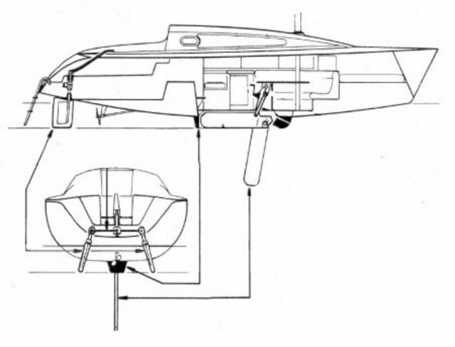 Due to bad maintenance the swing keel of my SunWay29 dropped while sailing in the English channel. This is how: The pivot bolt carved out the bedding in the cast iron keel bulb, making the holes oval allowing for 10 mm play, the port side screw securing the pivot bolt unscrewed bit by bit through the rocking motion of the boat and swing keel. Then while sailing endless miles with swell and wind from behind, the rocking motion made the pivot bolt exit through the starbord side completely. Banging noise. Boat uncontrollable. Keel dropped only held by the pulley, dangled in the water for a minute, acted as a second rudder causing a series of violent jibes, twisted and banged and finally sheared off @6.5 knots before I could realise what was going on. It took only a minute or so, 5BFt winds from behind and the dangling keel made the boat feel like trying to break in a horse while sitting backwards and grabbing its tail ... Now I am busy reverse engineering the geometry of the swing keel since a replacement part or drawings do not seem to be available. Any help, images, measurements or drawings appreciated of the keel geometry and construction. I already studied the threads of the SO30i and SO35 keel works, and the 29.2 swing keel repair. I also had the opportunity to take a look at a Fantasia 27 swing keel. Most puzzling at the moment: - What is the correct angle between swing keel leading edge and waterline when fully down - What is the center of gravity of the swing keel - Is the swing keel profiled like the SO30i or is it a blade more like the fantasia and the SO29.2 - What makes the swing keel rest in the correct down position - What is the correct swing keel geometry alltogether For the keel bulb repair: I was able to reverse engineer the exact centerpoint of the pivot bolt axis. Will construct a tool which will attach to the keel bulb as a guide to drill out the oval holes in the grey cast iron. It was 25mm, I wil drill them @ 30mm and insert a bushing reducing the diameter to the original 25mm. Bushings either a technical plastic like Delrin or bronze.  |
|
|
|
Post by MalcolmP on Apr 20, 2021 11:27:30 GMT
What a nightmare. Glad you were able to get back to port safely. Worth sending an email to service.client@jeanneau.fr They may have drawings of the lift keel they can share. Do include your HIN number and year of build. Similarly try Tony Castro the designer of the Sun Way 29 (aka Sun Odyssey 28.1) www.tonycastroyachts.com/As you may know there are some articles on a variety of Jeanneau lift keels in our Hints and Tips which may help. www.jeanneau-owners.com/hintsandtipsindexhull.htmlDo keep us informed of your progress. Malcolm |
|
xela
Junior Member
sailing
Posts: 12
|
Post by xela on Apr 20, 2021 20:38:44 GMT
What a nightmare. Glad you were able to get back to port safely. Worth sending an email to service.client@jeanneau.fr They may have drawings of the lift keel they can share. Do include your HIN number and year of build. Similarly try Tony Castro the designer of the Sun Way 29 (aka Sun Odyssey 28.1) www.tonycastroyachts.com/As you may know there are some articles on a variety of Jeanneau lift keels in our Hints and Tips which may help. www.jeanneau-owners.com/hintsandtipsindexhull.htmlDo keep us informed of your progress. Malcolm Thank you MalcolmP! Jeanneau does not have the SW29 plans anymore, that has been established. Now we're trying the SO28.1. I think I have any image that is google-able in the meantime. BUT: I dind't know www.tonycastroyachts.com/, many thanks for the tip! Considering the tool: I 3D printed a 150mm long prototype which tightly fits into the 60mm hole, with two ball bearings inside, and test-fitted it today. Seems to work as a guide for the outer part! Now I'll think about how to center it properly  I'll post updates.... |
|
|
|
Post by rene460 on Apr 22, 2021 10:20:41 GMT
Hi Xela, as Malcolm said, what a nightmare. As a long time owner of trailersailers, and now the SO30i, I have long thought that failure of the lift cable/rope would be the worst disaster, as it’s hard to get back to a launching ramp with the board down. I must admit that I never thought of the pin falling out. You have done well to get safely home after such an event.
Unfortunately I have no knowledge of the Sunway system, so can’t add much to your questions, though some features are common in some form to all the different systems.
You can see in the photos for the SO30i keel removal article, that the head of the keel has metal plates on the edge to stop the keel travel at the top and bottom of the travel. I have found that instead of leaving the board fully down, it sometimes seems helpful to adjust the balance of the rig by hauling it up just a little so it tilts more aft, thus shifting the centre of effort aft, an adjustment not available with a fixed keel. So I would not be too concerned about the limit, so long as it is a solid stop, with appropriate protective pad.
The tendency for the board to swing sideways on the 30i is resisted by those round pads you can see in the photos contained in the 30i and the 32 articles. As soon as there is any side force on the board, it quickly rests those pads against the inside of the keel box, and then does not move further. Of course, in the downwind conditions you experienced, the board does move back and forth a bit, and I tend to try and alter course a bit when feasible to settle things down generally.
I hope that is some help. Sorry that I have not more to offer.
I am impressed by your approach to re-machining that pin hole in place, you clearly have specialist knowledge there.
How that oval hole started, I don’t know, I wonder if the plastic bushes were left out at some stage, or if perhaps they were introduced in the later keel designs, just to prevent that corrosion. The stainless steel pin in the cast iron keel in sea water needs some thought to prevent corrosion. I have the plastic bushes, but also use a generous application of one of the anti corrosion compounds to provide some extra assurance, and re-application each year has worked so far.
rene460
|
|
xela
Junior Member
sailing
Posts: 12
|
Post by xela on Apr 22, 2021 23:17:13 GMT
Hello Rene, thanks a lot. Yes I was paying close attention to the thread of the SO30i, great work. I actually thought the stopping plates were plastic, good to know that they are made out of steel! And also I thought That helps a lot since I was already puzzled how to tight-fit them and keep them that way. Thanks for the information! Also the corrision part is one to really consider... Actually I like the design of the centreboard of the SO30i, clean shape and it is profiled. At the same time I'm a layman when it comes to hydrodynamics, and the original one might just be a blade. My concern is that by not applying the original shape I could end up with less performance...although there is a fair chance for improved performance as well. Update on MalcolmP's tip: Today I received a mail from Tony Castro! He does not have the original drawings since he wasn't allowed to keep those, but offered to help, I will share some more information with him. Amazing that he takes the time! Update on the drilling part: Since I have to drill out 30mm x 115mm in the cast iron after bridging a 25mm recess I researched which drill or cutter would be an option. There seems to be no standard solution that provides approx. 150mm drilling depth. I'm now thinking of modifying one of this type . Guiding it with a pin that centers it from the hollow inside and pecking a lot, otherwise it might get jammed quite easily...could that work or will it result in a bigger hole with a 'variable' diameter? Otherwise no progress, I had to work |
|
|
|
Post by MalcolmP on Apr 23, 2021 6:57:41 GMT
Glad Tony Castro replied, guess it makes a refreshing change to working on his latest superyacht and going back to basics! Such a shame he doesn't have the drawings...Did you go back to Jeanneau to check if they still have anything on the Sun Odyssey 28.1 that might help? I believe they are identical to the Sun Way 29 it was just a branding change.
|
|
|
|
Post by Charlie-Bravo on Apr 23, 2021 8:35:34 GMT
Your cutter idea isn't bad, and a new Starrett cutter would also work, the main problem with either is the control of the drilling machine, a pistol grip drill isn't really viable for an accurate result.
Either rent a mag mount drill and buy and adapt the cutter to follow the desired path, or better still , pop it to a machine shop who would breeze through the operation with a radial drill or mill in no time at all, and an accurate result ..... yes they will charge, but you might be pleasantly surprised , and they will do a better job, and could spin you up a new bush whilst they are at it. I like doing everything myself, but sometimes it is better to use people with serious machines.
I was looking at a lift keel 35, but happy I ended up with a deep fixed keel even though there are lots of places I can't go, there are still plenty of places I can.
Good luck with the rebuild
CB
|
|
xela
Junior Member
sailing
Posts: 12
|
Post by xela on Apr 23, 2021 9:32:39 GMT
Glad Tony Castro replied, guess it makes a refreshing change to working on his latest superyacht and going back to basics! Such a shame he doesn't have the drawings...Did you go back to Jeanneau to check if they still have anything on the Sun Odyssey 28.1 that might help? I believe they are identical to the Sun Way 29 it was just a branding change. Hello MalcolmP and all, Tony Castro wasn't allowed to keep the drawings unfortunately. The official Jeanneau dealer here tries to get the SO28.1 Drawings, no success so far. From what I found, the SunWay29 and the SO28.1 differ in deck layout, but the hull seems to have been made in exactly the same mold. When looking at the drawings in the owner's manual, the angle between waterline and fully-down centreboard. |
|
xela
Junior Member
sailing
Posts: 12
|
Post by xela on Apr 23, 2021 9:46:50 GMT
Your cutter idea isn't bad, and a new Starrett cutter would also work, the main problem with either is the control of the drilling machine, a pistol grip drill isn't really viable for an accurate result. Either rent a mag mount drill and buy and adapt the cutter to follow the desired path, or better still , pop it to a machine shop who would breeze through the operation with a radial drill or mill in no time at all, and an accurate result ..... yes they will charge, but you might be pleasantly surprised , and they will do a better job, and could spin you up a new bush whilst they are at it. I like doing everything myself, but sometimes it is better to use people with serious machines. I was looking at a lift keel 35, but happy I ended up with a deep fixed keel even though there are lots of places I can't go, there are still plenty of places I can. Good luck with the rebuild CB Thank you for the input CB! Good tip! I contacted a professional today. They will try to drill Wednesday next week in Situ. If they do not succeed we'll regroup... |
|
|
|
Post by rene460 on Apr 23, 2021 10:54:51 GMT
Hi Xela,
That cutter is known here as a rotary broach, or broach cutter. It is usually used in a magnetic base drill but requires a flat surface for the magnetic base to attach to. Definitely not a job for a hand held drill. I am glad that you have found a professional prepared to look at it with you. I will be interested to hear the outcome.
With those pads on the 30i, the ones on the sides of the board are plastic, screwed in place on the non- metallic board. For these I would also use plastic on your metal board, but the screws to hold them in place will require some thought. These are located so they rest against the inside of the casing at the top and bottom (when the board is in the down position) to resist the sideways forces/torque on the board. The pin is only a pivot, and plays no part in resisting the side to side movement. In fact, a very large number of trailerables were built using a slot, sloping down from the pivot point to the forward edge of the board, so the board could be easily removed, but I don’t recommend that approach.
The other pads I described earlier, are the ones on the edge of the board which stop the board at the top and bottom of its travel by resting against the inside of the cast iron keel case. In my case, these are metal, though plastic would probably also be suitable. For your metal board, I think I would use plastic for a bit softer contact point.
Personally, I would not worry if you cannot get a drawing showing the shape of the board, I would expect that what you reverse engineer to fit in the keel case will provide adequate side force, and the exact outline is not very critical. But it would be helpful to get an idea of the thickness they used, at least on similar size boats. You will be able to work out if any shaping of the head of the board (the part which stays inside the casing) is needed to ensure it does not pinch the lift cable, and to ensure that the required pads are in the appropriate places.
Regarding the profile, fluid mechanics gives a guide to the ideal shape which will give lower resistance to forward motion, but the limit is probably determined by the facilities you have available to shape the board. A bit of tapering on the aft edge, and a bit of rounding on the leading edge will be helpful if you can do it, but many of the trailerables which had plate centreboards were just cut with square edges, paint will adhere better around the corners if they are rounded a little rather than left sharp.
I hope the discussion is helpful in your deciding how to proceed.
rene460
|
|
xela
Junior Member
sailing
Posts: 12
|
Post by xela on Apr 23, 2021 12:00:44 GMT
Hi Xela, That cutter is known here as a rotary broach, or broach cutter. It is usually used in a magnetic base drill but requires a flat surface for the magnetic base to attach to. Definitely not a job for a hand held drill. I am glad that you have found a professional prepared to look at it with you. I will be interested to hear the outcome. With those pads on the 30i, the ones on the sides of the board are plastic, screwed in place on the non- metallic board. For these I would also use plastic on your metal board, but the screws to hold them in place will require some thought. These are located so they rest against the inside of the casing at the top and bottom (when the board is in the down position) to resist the sideways forces/torque on the board. The pin is only a pivot, and plays no part in resisting the side to side movement. In fact, a very large number of trailerables were built using a slot, sloping down from the pivot point to the forward edge of the board, so the board could be easily removed, but I don’t recommend that approach. The other pads I described earlier, are the ones on the edge of the board which stop the board at the top and bottom of its travel by resting against the inside of the cast iron keel case. In my case, these are metal, though plastic would probably also be suitable. For your metal board, I think I would use plastic for a bit softer contact point. Personally, I would not worry if you cannot get a drawing showing the shape of the board, I would expect that what you reverse engineer to fit in the keel case will provide adequate side force, and the exact outline is not very critical. But it would be helpful to get an idea of the thickness they used, at least on similar size boats. You will be able to work out if any shaping of the head of the board (the part which stays inside the casing) is needed to ensure it does not pinch the lift cable, and to ensure that the required pads are in the appropriate places. Regarding the profile, fluid mechanics gives a guide to the ideal shape which will give lower resistance to forward motion, but the limit is probably determined by the facilities you have available to shape the board. A bit of tapering on the aft edge, and a bit of rounding on the leading edge will be helpful if you can do it, but many of the trailerables which had plate centreboards were just cut with square edges, paint will adhere better around the corners if they are rounded a little rather than left sharp. I hope the discussion is helpful in your deciding how to proceed. rene460 Hi rene460 , thanks again! The slot may just be the tittle thing in the drawing at the pivot bolt location that I couldn't interpret yet...And for sure this is helpful! I will post some images.. |
|
|
|
Post by MalcolmP on Apr 23, 2021 14:15:48 GMT
Glad Tony Castro replied, guess it makes a refreshing change to working on his latest superyacht and going back to basics! Such a shame he doesn't have the drawings...Did you go back to Jeanneau to check if they still have anything on the Sun Odyssey 28.1 that might help? I believe they are identical to the Sun Way 29 it was just a branding change. Hello MalcolmP and all, Tony Castro wasn't allowed to keep the drawings unfortunately. The official Jeanneau dealer here tries to get the SO28.1 Drawings, no success so far. From what I found, the SunWay29 and the SO28.1 differ in deck layout, but the hull seems to have been made in exactly the same mold. When looking at the drawings in the owner's manual, the angle between waterline and fully-down centreboard. Do send an email to service.client@jeanneau.fr in case they have keel details for the SO28.1 Interesting about the deck layouts differences |
|
xela
Junior Member
sailing
Posts: 12
|
Post by xela on Apr 24, 2021 7:44:24 GMT
Hi all, @malcolmp the mechanic of GlobalNautique here is chasing after the SO28.1 drawings @ Jeanneau for this project. I will also send a mail! I added images in the attachment. The single image is from a classifieds ad of a SO28.1, the best image of the centerboard yet. Something struck me which might solve the 'down position fix' piece of the puzzle: I looked at the image in the beginning of the thread, the B&W from the Jeanneau owner's manual, to reconstruct the geometry. If you take a close look then there is a white space where the centerboard and keel bulb would meet. Looks like a recess. I thought the centerboard geometry must have a corresponding lip of some kind, which was a guesstimate from the drawing. But in Fusion360 where I do my reverse engineering, taking the measured dimensions, there is no way any feature could meet the recess in a proper way while also being unexposed once the centerboard is up. Now I think that the feature inside the nose of the keel bulb, this recess, actually might be a drawing issue, and in fact there has to be material. That would make partly sense from the geometry. If I take a look at the last images in the inspection keel box file with this premise in mind, it also could be possible that the recess actually is the result of a chipped-away piece in form of a wedge. The weight of the centerboard could have pounded that away in the course of years. The 'volcanic' structure of the material off-center could indicate that. It makes sense to me that the cast iron would crystallize in such a way, and this is the part with the least volume in the casting, so I wouldn't be surprised to find more stress there from cooling than elsewhere. Could be another cause of the final failure, allowing for excessive play in the first place. The middle could have been grinded smooth by the centerboard dangling loosely in the pivot bolt. I might have fooled myself into assuming that the recess is there on purpose because of the coincidental resemblance with the drawing. If so it means I would have to reconstruct that wedge as well or find a way to cope with the missing geometry. Any second opinions/idea's about this analysis?  |
|
xela
Junior Member
sailing
Posts: 12
|
Post by xela on May 3, 2021 15:25:17 GMT
...meanwhile...an update: Tony Castro helped out with valuable reassurance. Here is the current design which I will prototype using plywood and see how it works. The part exposed to the waterflow will receive a NACA Profile which is parallel with the waterflow in the down position when close-hauled.   |
|
|
|
Post by MalcolmP on May 3, 2021 15:41:19 GMT
Excellent progress, so glad for you that Tony Castro is giving input.
|
|
xela
Junior Member
sailing
Posts: 12
|
Post by xela on May 3, 2021 15:48:15 GMT
Excellent progress, so glad for you that Tony Castro is giving input. Yep, really great!! |
|
xela
Junior Member
sailing
Posts: 12
|
Post by xela on May 12, 2021 19:19:41 GMT
Update: I fabricated a wooden mock-up which I could test-fit and install. I had to trim approx. 10mm off the sole. Otherwise it fitted well and worked like a charm. After that I made some slight changes to the design, added a foil using Chris Drake's fantastic airfoil program which can be found here chrisdrake.com/Airfoil_Tools/ and rendered the final version which I will order at a metal shop these days. Seriously impressed with Chris Drake's work, which allows for configuring a lot of parameters like the medium type ' salt water' and its properties. He designed and 3D printed an underwater pool glider...absolutely take a look at this program for designing any kind of profile, for rudders, hydrofoils, keels and so on. The overall volume of the swing keel replacement design is about 8400cm3 and the weight just north of 60kg which sounds reasonable enough to me. Here are a few renderings, I will update again once the thing has been made...    |
|
|
|
Post by MalcolmP on May 13, 2021 14:40:48 GMT
Very impressive 👍, will work better than go-faster stripes for sure. Once it is all complete would be good to use this thread to create a Hints and Tips article which should last a d help others in the future with a similar nightmare.
|
|
|
|
Post by ucapajr on Apr 17, 2023 15:46:59 GMT
Update: I fabricated a wooden mock-up which I could test-fit and install. I had to trim approx. 10mm off the sole. Otherwise it fitted well and worked like a charm. After that I made some slight changes to the design, added a foil using Chris Drake's fantastic airfoil program which can be found here chrisdrake.com/Airfoil_Tools/ and rendered the final version which I will order at a metal shop these days. Seriously impressed with Chris Drake's work, which allows for configuring a lot of parameters like the medium type ' salt water' and its properties. He designed and 3D printed an underwater pool glider...absolutely take a look at this program for designing any kind of profile, for rudders, hydrofoils, keels and so on. The overall volume of the swing keel replacement design is about 8400cm3 and the weight just north of 60kg which sounds reasonable enough to me. Here are a few renderings, I will update again once the thing has been made... Hi Xela, Looks like you have got it sorted! Good job with the replacement! I have a similar issue, I have the CB but it’s now banana shaped!! I’ll looking at getting it straightened but it might be easier to get a replacement fabricated. Does anyone know what grade of steel I should specify to the fabricators? Cheers, Andy |
|


