|
|
Post by MalcolmP on Sept 22, 2014 7:15:20 GMT
A few weeks ago I installed a Victron current meter BMV 700 and shunt and had been getting unexpected low readings, but then had to leave the for a couple of weeks before I could investigate further. But this weekend after taking the batteries out I found to my surprise that there are 2 negative returns wired to both ends of the battery bank (the one I could not see easily as the terminal was under the woodwork, these must have been there since new). So the main part of the mystery was solved as I connected the shunt to the other return (which must have the main loads) see sketch and now the current meter is working well. I have yet to have time to try to trace where the second return comes from - but I presume that I should be able to connect both of these to the far side of the shunt - there is only 1 positive feed. Confirmation and/or comments greatly appreciated - seems weird they didn't go to the same terminal even though of course they are connected by the jumper wires.. 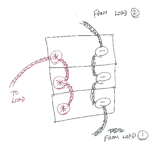 Attachment Deleted Attachment Deleted Malcolm |
|
|
|
Post by krawall on Sept 22, 2014 7:51:51 GMT
Hi Malcom,
maybe i read your post wrong, but one would go to the switch and terminate the negative load from the system, the other one would go to common ground of the boat...
Makes sense?
Tom
|
|
|
|
Post by hoppy on Sept 22, 2014 8:30:26 GMT
From what I understand, the correct wiring should be using the Load (1) negative for a more balanced discharge.
Google marine battery wiring. I could not see an example of wiring like you have
|
|
|
|
Post by jez on Sept 22, 2014 10:14:33 GMT
Malcom
Its not that unusual to have several cables in low voltage/high current applications. Two smaller crimp connected cables are often better than one big one in terms of flexibility, heat disipation, reliability and for Jeanneau, probably cheaper.
Also for battery charging, any small volt drops in the cables that stop the charger seeing true battery terminal voltage when currents are high can be significant.
One thing that Jeanneau did not do correctly on my boat, is use the 3rd unused split charge diode for the alternator bat voltage ref, but thats a bit off topic.
Is one of the cablea going to the engine block?
Jez
JEZ
|
|
|
|
Post by sitara on Sept 22, 2014 21:30:53 GMT
Hi Malcom,
Is this wiring shown on the boats circuit diagram? This would show how Jeanneau intended it to be wired compared to how it was actually wired.
|
|
|
|
Post by MalcolmP on Sept 23, 2014 6:17:46 GMT
Thanks for all the replies. I am not on the boat at the moment so can't check the OEM wiring diagram, but will at weekend. I suspect as others indicate the second wire is an earth probably from the engine . They are large cables - the same size as the positive - IE like automotive starter size. Presuming it is an earth then I guess I can leave where it is rather than rewire from the far side of the ammeter shunt?
|
|
|
|
Post by electricmonk on Sept 23, 2014 14:30:55 GMT
For what it's worth when my SO43 was new it had the same schema, the "spare" negative on the end of the house bank was connected to the starter battery negative. It didn't stay like that for long! Its not that that is "wrong" its just that its not "right" if you get what I mean. What ever you decide to do about it please don't just leave it dangling, if its redundant cut it off; one less unexpected challenge to face in the future.  |
|
|
|
Post by krawall on Sept 24, 2014 9:28:14 GMT
Thanks for all the replies. I am not on the boat at the moment so can't check the OEM wiring diagram, but will at weekend. I suspect as others indicate the second wire is an earth probably from the engine . They are large cables - the same size as the positive - IE like automotive starter size. Presuming it is an earth then I guess I can leave where it is rather than rewire from the far side of the ammeter shunt? Actually, if you are right, then no, you can't because the shunt needs to go between the negative of the battery and the load - and some load may be connected to the common ground and this will then not be registered. So I guess you have to find out where it goes and if it goes to the engine block or other grounding, then this needs to be combined on the other side of the shunt. You said you got a really low reading when connected to the other one and that indicates that something is using that other ground cable. Tom |
|
|
|
Post by MalcolmP on Sept 24, 2014 11:33:20 GMT
For what it's worth when my SO43 was new it had the same schema, the "spare" negative on the end of the house bank was connected to the starter battery negative. It didn't stay like that for long! So I guess you have to find out where it goes and if it goes to the engine block or other grounding, then this needs to be combined on the other side of the shunt. You said you got a really low reading when connected to the other one and that indicates that something is using that other ground cable. Tom Thanks guys for that feedback - yes looks like I will rewire so that the are both on the far side of the shunt Electricmonk - just to clarify, did you remove the OEM wire that linked that starter negative to the house-bank entirely or rewire to connect it to the end of the house-bank the same as the main return? Thanks Malcolm |
|
|
|
Post by electricmonk on Sept 24, 2014 14:47:23 GMT
In the diagram above I would take the wire labelled negative from load 2 and remove it - so the cells are in parallel but "balanced" via the negative labelled load 1. It's believed that wired that way you get better utility from the bank.
Then I would provide a completely separate negative for the starter bank I assume that to be load 2.
yes they may both end up on the same bolt but there is less chance of a high resistance as there are fewer dependencies especially for the starter bank.
|
|
|
|
Post by MalcolmP on Oct 7, 2014 6:33:23 GMT
Just remembered to update this thread. Changed the wiring a few weeks ago so that both negatives are the far side of the shunt and the BMV is now working perfectly. Thanks for all the advice.
|
|


