|
|
Post by mred25234 on Sept 7, 2013 14:31:46 GMT
I finally got around to installing the timer as discussed earlier in this thread. The timer I originally purchased for this was not suitable so I purchase another with a different configuration like this. The timer is found if you search on "12 volt 10Amp Adjustable TIMER relay ALT/ADJTIMERRELA" on Ebay and was delivered from the UK. The sump pump looks like this and is found under the aft head sink.  The connections to the timer only have to be made at these existing connections.  The installed product is shown in this photograph  The timer has a switch to roughly set the duration and nature of operation and a control to finely set the timer duration. We considered what is the most logical time required and thought that the time it takes to empty the floor of the shower from the time the waste water just covers the floor grate. That was timed to be 25 seconds. We have consequently set the timer to 25 seconds. So now when having a shower, when the water covers the floor grate you can press the shower sump switch and it will keep the sump pump working until the floor waste is empty. More details available if anyone is interested in doing this themselves and any of it is not clear. Trevor Bird Where is the Filter located? |
|
|
|
Post by Trevor on Sept 7, 2013 19:03:31 GMT
Hi Brent,
No the switch is the same as original and is untouched. You simply push the switch and release it and the timer does the rest. The only place you need to connect to is plugs or sockets that connect to the switch and the pump under the sink in the aft head.
Regards,
Trev
|
|
|
|
Post by Tafika II on Sept 10, 2013 21:09:37 GMT
Hi Trevor!
THanks on the switch update. I order two timer relays. I'll let you know how the install goes or email you if I have any questions.
Thanks!
|
|
|
|
Post by ForGrinsToo on Sept 10, 2013 21:26:32 GMT
Here's where a electromagnetic valve comes in handy. Before showering I (we) press a button and the showerwater is diverted to the tank again. That takes about max. 1 minute and the showerwater is at the right (preset by the thermostaic valve) temp. After soaping in , the same procedure rules. To make a long story short , a relay like yours could avoid having to press the return button during the reflux period. Sailbleu, This is a great idea, using a solenoid valve and divertor. I think I know how I would do it but would really appreciate it if you would post some details - ideally to Hints and Tips. Geoff |
|
|
|
Post by sailbleu on Sept 11, 2013 4:00:14 GMT
More than willing to help you out Geoff , but you see the solenoid thing is just a part of a bigger whole. I'm sure you read the section where I mention that I've installed a thermostatic valve supplying us the right (set) temp at all times. That gave me a chance of diverting the ' mixed ' (hot/cold) water towards the watertank . It takes less than 30 seconds to get the temp. right After releasing the button all is set to shower. Of course , if you dont have a thermostatic valve ( which I absolutely recommend considering the luxery you get) you can also divert only the hot water. It all a matter of avoiding that cold schock at the start of each shower. Additionally you also save water , no doubt about that. It did came to my mind to present it for the hints & tips. I have all the pics of the modification on the hard disk here ,....... somewhere  I never got around on posting it you see. Maybe this comming winter , so if you have the time to put things on hold. Hope that helps. Regards |
|
|
|
Post by Tafika II on Sept 19, 2013 13:33:03 GMT
Hi Trevor,
I just received the timers from the guys in the UK. Easy & fast service. In order to get the 25 second on time, how are your two rotator A and B dials set?
Thanks!
|
|
|
|
Post by Trevor on Sept 20, 2013 2:42:54 GMT
Hi Brent, The timer switch is set to position 1. That is the lower switch in the photo below. The other rotary control is set to make the timer 25 seconds. That has to be done using the "trial and error method".  I hope this helps. Regards, Trev  Attachment Deleted Attachment Deleted |
|
|
|
Post by Tafika II on Sept 20, 2013 15:43:58 GMT
Hi Trevor! I got the setting OK on the timer, but the wiring is challenging me a little. Before I start cutting wires, it looks as if you may have used some existing connectors or bought new white ones. I have the 5 pin automotive connectors with 5 wires coming out the back. I assume to connected them to another connector as your installation looks neat and without wire nuts or terminals. Maybe you can shed some light on this for me please. I posted this on your messages also. is a PDF diagram of how I foresee the wiring. Can you help confirm this is correct or advise what I need to change. As always, you assistance is appreciated. Best regards, Brent 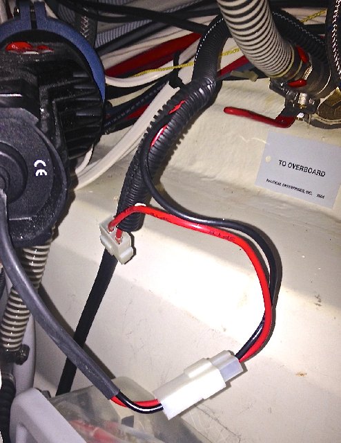 ![]() 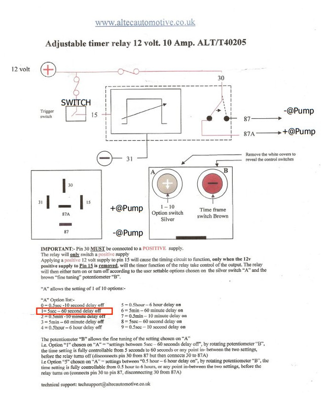 |
|
|
|
Post by Trevor on Sept 21, 2013 12:49:02 GMT
Hello Brent,
I tried to not cut any wires. I like being able to go back to original if the relay fails.
I soldered to the terminals where the cable is crimped inside the white connector housing. I removed the terminals by sliding a very thin flat blade screwdriver ( Jewelers screwdriver ) down beside the terminal which pushes back a small tab that holds the terminal into the white plug or socket housing.
I removed the terminal coming from the pump (red wire) and connected that one by using a spade terminal on the wire coming from pin 87 of the relay. I then put heatshrink over that connector just to tidy it up.
Just referring to your drawing.
Pin 30 …..good….solder to lower red wire on upper connector in your photo.
Pin 15……good….solder to upper red wired on upper connector in your photo.
Pin 31……solder to black wire on lower connector on your photo. This is simply the negative supply to the timer circuit.
Pin 87……Remove red wire (coming from pump) from lower white connector in your photo. Using a spade terminal, connect to pin 87 of relay. Heatshrink over the connector if you would like to cover it and ensure it will not come apart.
Pin 87A....not connected.
The timer will start when the voltage is removed from pin 15. This means you push the switch and release it and when released the relay powers the pump for the predetermined time.
If the relay fails, simply push the removed terminal back into the original connector housing and you are back to factory installation.
Let me know if this does not help and I will get back to you with a drawing.
I hope this helps,
Regards,
Trevor
|
|
|
|
Post by Tafika II on Sept 23, 2013 15:31:56 GMT
Trevor...thanks. I'll get on this project next week. New problem arose Sunday while motor sailing...diesel smell...either a leak at the tank or exhaust. Nothing in the bilges. More fun!
|
|
jeffc
New Member
Posts: 4 
|
Post by jeffc on May 17, 2014 21:25:26 GMT
Hello Brent, I tried to not cut any wires. I like being able to go back to original if the relay fails. I soldered to the terminals where the cable is crimped inside the white connector housing. I removed the terminals by sliding a very thin flat blade screwdriver ( Jewelers screwdriver ) down beside the terminal which pushes back a small tab that holds the terminal into the white plug or socket housing. I removed the terminal coming from the pump (red wire) and connected that one by using a spade terminal on the wire coming from pin 87 of the relay. I then put heatshrink over that connector just to tidy it up. Just referring to your drawing. Pin 30 …..good….solder to lower red wire on upper connector in your photo. Pin 15……good….solder to upper red wired on upper connector in your photo. Pin 31……solder to black wire on lower connector on your photo. This is simply the negative supply to the timer circuit. Pin 87……Remove red wire (coming from pump) from lower white connector in your photo. Using a spade terminal, connect to pin 87 of relay. Heatshrink over the connector if you would like to cover it and ensure it will not come apart. Pin 87A....not connected. The timer will start when the voltage is removed from pin 15. This means you push the switch and release it and when released the relay powers the pump for the predetermined time. If the relay fails, simply push the removed terminal back into the original connector housing and you are back to factory installation. Let me know if this does not help and I will get back to you with a drawing. I hope this helps, Regards, Trevor I just want to thank all who have contributed to the shower relay conversation. I just installed two sets of these in my Prestige 42 fly. I could not have done it without the diagrams and instructions. Thank you all. Jeff |
|
|
|
Post by alenka on May 18, 2014 7:06:26 GMT
Just a thought...
What happens if the sump is dry and there is no water to pump before it times out? If the pump is left with nothing to eject will it start to run hot and eventually burn out?
I know from expereince if you run your engine with the water inlet closed the impellor last only a few seconds before it disintegrates!
|
|
|
|
Post by dnickj on May 18, 2014 18:20:44 GMT
Hi I installed a programmable delay switch duration anything from 1 to 30 min just one touch of the button pump runs then turns off after the pre set delay when on standby it only draws a few milli amp
Regards
Nick
Sent from my iPhone using Tapatalk
|
|
|
|
Post by Trevor on May 19, 2014 2:30:10 GMT
Hello Alenka,
I have been advised that the pump can run dry without any detrimental effect. It is a different design to the engine water pump.
Regards,
Trevor
|
|
jeffc
New Member
Posts: 4
|
Post by jeffc on May 20, 2014 1:19:55 GMT
Just a thought... What happens if the sump is dry and there is no water to pump before it times out? If the pump is left with nothing to eject will it start to run hot and eventually burn out? I know from expereince if you run your engine with the water inlet closed the impellor last only a few seconds before it disintegrates! It all depends on the pump. In my case it is a diaphragm pump (no impeller) that can run dry. |
|
|
|
Post by On y va on May 20, 2014 7:21:21 GMT
I think most Jeanneau´s of that era have the "handheld" shower activation switch. It is a bit of a nuisance yes, but what adoyabn describes is the thought behind it. In these days, watermakers weren´t that common, expecially not on smaller yachts. One conversion we have done in a Beneteau 50 (which has the same system) was to install a sump box with a float switch. We only did one, in the owners cabin shower. Quite a bit of fiddling with the hoses. But it worked ok, as long as you didn´t have women on board with long hairs. I will stick with my simple spring switch. |
|
|
|
Post by learn2sail on Nov 17, 2016 23:55:36 GMT
Dear Trevor, I found/read the shower sump pump delay off switch thread while searching for a delay off switch for my new 2017 Beneteau Oceanis 37'. The photos you showed under the sink have pumps and installation identical to what I have on my boat. So, I ordered the adjustable timer relay from www.altecautomotive.co.uk and it to is just like the one you picture. Well, I think I'm going to have an electrician do the work, as it doesn't look so much like "plug and play" and I don't want to screw it up. And I could use some help on setting the timer as you did, for a 25 second delay. Even with your directions, and those that came with the relay, I can't figure on what number to put the A option switch silver on, and the B option time frame switch brown to. Any help you can offer would be greatly appreciated. Love all these posts as they apply so well to a Beneteau as well. Thank you. Lee |
|
|
|
Post by Trevor on Nov 20, 2016 12:29:49 GMT
Hi Lee, Have you seen this? It may or may not help you but I am just checking if you seen it. www.jeanneau-owners.com/hintsandtips/showersump.htmlPut the switch on position one ( delay off timer 5-60 seconds) and simply set the acurate time of the timer with the other adjustment 15 comes from the original sump switch and 87 now goes to the pump. Let's know if this helps or not? Regards, Trevor |
|
|
|
Post by mickmeck on Oct 4, 2017 15:58:13 GMT
I finally got around to installing the timer as discussed earlier in this thread. The timer I originally purchased for this was not suitable so I purchase another with a different configuration like this. The timer is found if you search on "12 volt 10Amp Adjustable TIMER relay ALT/ADJTIMERRELA" on Ebay and was delivered from the UK. The sump pump looks like this and is found under the aft head sink. The connections to the timer only have to be made at these existing connections. The installed product is shown in this photograph The timer has a switch to roughly set the duration and nature of operation and a control to finely set the timer duration. We considered what is the most logical time required and thought that the time it takes to empty the floor of the shower from the time the waste water just covers the floor grate. That was timed to be 25 seconds. We have consequently set the timer to 25 seconds. So now when having a shower, when the water covers the floor grate you can press the shower sump switch and it will keep the sump pump working until the floor waste is empty. More details available if anyone is interested in doing this themselves and any of it is not clear. Trevor Bird I also purchased this switch. In reviewing the schematics of the switch it has 5 pins. When I look at your picture you only have two wires attached. Do you have an always on/always off switch? How does the timer get its power to run the timer? If it is as simple as just putting in line on the power side of the switch then consider this job done. Otherwise, I need to know what is really happening, if you could elaborate please. Thanks in advance. Mick Meckler |
|
|
|
Post by Trevor on Dec 3, 2017 1:38:20 GMT
Hello Mick,
Sorry for the late response. I hope I can help.
The timer relay I installed had four wires. It does need a constant power source, a negative (or ground) connection, it needs the wire from the switch to trigger the timer and the connection to the pump motor.
Constant 12Volt power for the timer goes to pin 30. This will also supply the power to the pump motor when the timer is activated. The supply connection to the pump red wire is from pin 87. The voltage from the switch in the shower cubicle goes to pin 15. The black wire connection goes to pin 31 on the timer and is the ground connection for the timer.
It looks a bit like I only used two wires in the photo but in fact used 4. I was a bit remiss in using a red wire for the ground connection. I must have only had red wire handy and decided to use that. A bit naughty but electrically ok.
All of the power sources are available under the aft sink in the 42DS.
I hope this helps and sorry for the very late reply.
Regards,
Trevor
|
|
|
|
Post by saltymetals on May 9, 2018 15:24:14 GMT
Fabmod indeed! I know this is an old thread and i wish to make a vote of thanks to Trevor for having worked it out but i only now got round to also fixing my second shower with the same relay. I have a 2004 43ds and that switch in the shower was most annoying. i only purchased one relay to start with to see if i could wire it up and how it works. You don't need to change the switch and it is pretty straightforward wiring. Make sure you have a good crimping device I use the CK 30021 as recommended by Nigel Calder. I then bought a second relay and did the same setup for my other shower. I find the adjustable timer needs to be set close to the minimum on the relays i bought and this gives about 30 seconds on the pump which is adequate to empty the sump. Do not get a 5 minute timer bec this will then have yr pump running dry and simply consume more power for nothing. 30-40 seconds is all that is needed. During a typical shower you might run it 3 times. Just flip the switch momentarily downwards and let it go. Magic. I am sure you can get these things from all sorts of suppliers. i got mine online from www.altecautomotive.co.uk . Make sure you specify the right voltage (12 or 24V). You might find them cheaper on eBay but i paid £31 inc VAT for each relay plus £3 postage. I just wanted to be sure that i got the right ones rather than taking potluck on eBay. Andrew "Genial Bee" currently Certosa Marina/Venice. |
|
|
|
Post by buddyseattle on May 9, 2018 17:17:39 GMT
Here is another option.
On our 39I we installed a Water Witch in the small collection area under tthe shower grill. It holds about 1/2 a gallon so that when it partially fills, the pump kicks on and runs for about 10 seconds to clear the sump. It was easy to install, and works very consistently and effectively. There are no moving parts and requires no maintenance. We left the manual switch connected so you can use it to clear any other partial water in the line.
|
|
|
|
Post by freeflow on May 28, 2020 21:49:45 GMT
|
|
|
|
Post by mickmeck on May 28, 2020 22:29:52 GMT
I too didn't like the intermittent switch and was going to install the timer switch (I even bought 2) but after exploring the installation requirements I decided on just a plain old toggle switch. A no brainer. The pump is sufficiently loud that no one really could accidently leave it on. You run it when the water is high and turn it off when you hear gurgling. As for the drain not being able to keep up with the water - certainly it could be the filter is clogged, the line is blocked, or your water supply is too much. If it is the latter then you might want to throttle it back before you constantly run out of water.
I have two switches and the instructions if you find you would like to have a semi-automated solution. But, the wiring requirements are much greater than just replacing with a simple toggle swith.
|
|
|
|
Post by NZL50505 on May 28, 2020 22:30:13 GMT
Anyone know if a standard 42DS has filters / strainers for each of the showers and if so where are they located? I haven’t considered this before in 2 yrs of ownership...
|
|


