|
|
Post by so36idavid on Aug 6, 2014 22:29:46 GMT
Greetings, I have a 36i (2007). I'm currently going through my charging circuit in order to understand some performance issues. I'm wondering what is the point of the solenoid that is in series between the alternator and the batteries. For reference here is the circuit diagram and here is the solenoid. The solenoid in question is number 73 in the diagram. My first thought was that it closes sometime after starting the engine in order to keep the alternator load off when starting. But it would make more sense to do that in solenoid number 95, i.e. don't power the field coils of the alternator until the engine is running. What would be the downside of removing solenoid 73? While we're solving mystery components, what's the point of the breaker that disconnects the battery ground from the engine (number 70)? I can't imagine a scenario when I'd open that breaker so I'm tempted to wire around it. B.t.w. for the curious my (internally regulated) alternator is putting out 14.3V but the batteries are only seeing 13.2V. The difference is in the voltage drop in the crappy wires that Jeanneau used and the many connections between the two. I'm replacing a bunch of wires and ripping out as many connections as possible. Using an externally regulated alternator would raise the voltage at the batteries but there would still be a lot of losses in the wiring. So it's worth going through the exercise anyway. Thanks in advance David |
|
|
|
Post by so36idavid on Aug 7, 2014 3:57:05 GMT
Ah I get it, it isolates the two battery banks when the engine isn't running. So that clears up that mystery.
Still wondering about the breaker in the ground path...
|
|
|
|
Post by no3l on Aug 7, 2014 22:26:51 GMT
Hi David,
Did you intend to include the wiring diagram, I would be very interested in seeing it?
Rgds
Noel
|
|
|
|
Post by mikebz on Aug 7, 2014 23:15:46 GMT
Ah I get it, it isolates the two battery banks when the engine isn't running. So that clears up that mystery. Still wondering about the breaker in the ground path... Same relay as our SO32 had. The way I look at it is that it parallels up the starter and domestic banks when the alternator is charging - same thing really but I don't think it's a very nice solution. If you are losing 1.1V between the alternator and batteries when the batteries are reasonably well charged (i.e not drawing much current) then there is some badly wrong - and your batteries will never be properly charged. 13.2V is low for a float voltage let alone bulk charging. |
|
|
|
Post by windward54 on Aug 8, 2014 14:46:20 GMT
Sounds like what happened on our boat (49DS). We had a Newmark battery isolator installed in the charging circuit. The isolator went bad and was dropping a couple of volts in the charging circuit to the starter battery. The isolator was also getting very warm to the touch. I replaced it with a Blue Seas ACR and all the issues cleared up.
|
|
|
|
Post by pbunning on Aug 8, 2014 19:15:38 GMT
This looks similar to the wiring diagram for the SO33i. To understand the operation, it is also necessary to refer to the Yanmar manual for engine wiring. Jeanneau and Yanmar do not use the same terminology so I will try to illuminate.  See also photo of my alternator. The alternator effectively has two diode bridges, one to supply power to the battery (charging), the other for internal use - I assume to provide the alternator output voltage sensing for the internal regulator. i.e. it prevents the regulator being influenced by any external factors. Output to the batteries B+ on the diagram. The second output is D+ (Jeanneau diagram). Jeanneau also use this output and my guess the reason they have incorporated relay 95 is to prevent any load on this circuit (which may impact the sensing function). I think the diagram may be a bit misleading - it is the voltage at D+ that energises the coil of relay 95, When relay 95 closes, power from the starter battery/alternator via 7.5A fuse is provided to relay coil 73 and windlass permissive relay 79. Refer to photo - double connector has blue/black and red/black wires these correspond to L and R (Yanmar diagram) - D+ and not shown (Jeanneau diagram). Orange wire - tacho, Red - B+, B- hidden behind engine. On my boat, I found a relay tied into the wiring loom port side behind the alternator, which I think is relay 95. Hope this helps - if anyone else is better informed, I'd be interested also. Peter |
|
|
|
Post by so36idavid on Aug 9, 2014 6:05:17 GMT
Hi David, Did you intend to include the wiring diagram, I would be very interested in seeing it? Rgds Noel Noel, This is the image that I linked above. It's the part of the wiring diagram that's relevant to this discussion. 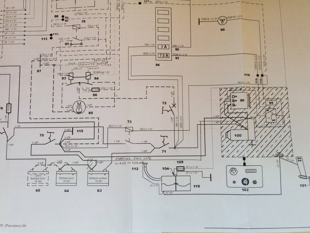 imgur.com/Z93b4iM imgur.com/Z93b4iMB.t.w. I'm still wondering why there's a breaker in the ground circuit (number 70). Anyone have any ideas about the point of this? David |
|
|
|
Post by ForGrinsToo on Jan 25, 2015 0:47:02 GMT
Hi David, and everyone: I'd like to follow up on this as I try to understand the wiring in our 2010 36i. First, in the wiring diagram #70 is a switch, not a breaker. I suppose at some point one might want to isolate the batteries totally. Even so, it seems the Cristec CPS2 OEM feeds on the battery side of 69, 70, 71 SO36I_12V_Diagrams.pdf (115.34 KB) and, as far as I can tell the Cristec really doesn't isolate the house and start batteries very well (if it does, or should, I must have bad diodes). Am I missing something? Geoff |
|
|
|
Post by pbunning on Jan 25, 2015 13:25:41 GMT
I understand the Cristec charger isolates the supplies via diodes, hence it is connected directly to the batteries.
|
|
|
|
Post by so36idavid on Jan 26, 2015 3:12:40 GMT
Geoff,
The Cristec is connected directly to the two battery banks so that it can charge them both when connected to shore power. When not connected to shore power it internally isolates the two. Exactly how it does that I'm not sure, it wouldn't surprise me if it has some power MOSFETs driving the output voltage.
When plugged into shore power I would expect your two battery banks to show the same voltage (mid 13s) which is being driven by the Cristec. When not plugged into shore power I would expect the two banks to show different voltages. As you draw power from the house bank the voltage will drop while the starting battery should stay rock steady. If it doesn't then indeed something is not isolating the banks. It's either the Cristec or the isolation relay. If this is indeed what you're seeing I would remove the connections one at a time from the starting bank and continue the experiment until you figure out which component is shorting the two together.
David
|
|


