

Emergency rudder & emergency propulsion
Dec 4, 2019 17:27:56 GMT
Post by sailbleu on Dec 4, 2019 17:27:56 GMT
A lot has been said about rudder failure and/or engine failure , non of both are recommendable , to say the least .
Now and then an article pops-up on the board of boaters having to deal with one of these ordeals. I read them too and hope like most of you it never happens us .
But why not be prepared , in the past I often played with the idea of adding an emergency propulsion of some sort in case of engine breakdown , clogged diesel filter , you name it . I'm aware of the use of the dinghy and outboard for that purpose , even experimented with it just in case , but what if it's deflated for whatever reason ?
Our scheduled Trans-Atlantic crossing ( no dinghy on deck or davits) next year made me reflect and re-think on what's possible . I came up with a concept where my setup would allow a back up propulsion as well as an emergency rudder.
On the internet , youtube , we can find some devices to tow behind the boat , permitting a rudimentary steering , some diy's constructed their own redundancy systems , most of them have a not so interesting aesthetic outcome , but they do work .
My intention was to design a configuration which is not dominantly present ( keep the swim platform clear) , can be assembled & disassembled in no time and stored when not in use , and of course is multi-functional.
The solution was a hook-up system in combo with an outboard mount that can be taken away and also can be used for multiple purposes .
1 : E-propulsion
2 : E-rudder
3 : step for easy dinghy access and vice versa
4 : cruising hydro generator
5 : who knows ?
Let me guide you through my approach , it might be a jump start for others or give you some ideas , at your discretion.
The first few pictures illustrate the tests of both systems , what follows is how I tackled it , how it came about ; and supplementary comments
www.23hq.com/sailbleu/photo/63236736/original
Not a very clear image , but the rudder test was done on the leg between the islands of El Hierro ( most south west canary island) and La Palma last summer. 2000 meters deep I took no chances of something breaking off and attached a safety line to the davits above . The sails were in and the engine speed was 5kts , the main rudder was in brake mode an neutral position , the E-rudder performed flawlessly and made 360 turns without hesitation .
www.23hq.com/sailbleu/photo/63231413/original
The E-propulsion test was done on the island La Gomera ( Canary islands). Safety line obligatory , and you will notice there was quite some cavitation going on due to the outboard not going deep enough . A formality as I have 3 height positions on the outboard mount , here the middle was used , obviously the lower level is required . The throttle was halfway and check the next photo for the speed result .

www.23hq.com/sailbleu/photo/63231714/original
Sailing from the quay to the anchorage in the bay on the west side of La Gomera , I made 2,6 kts , half throttle , and outboard not properly immersed , not bad for a 6 HP 4stroke outboard pushing an 8 ton boat don't you agree .

www.23hq.com/sailbleu/photo/63231959/original
This is where it all started , I call this the adapter plate ( right) and the back plate ( left) . The adapter plate will remain visible at all time , this will permanently stay on the transom and the required back plat will offer some strength as the transom fiberglass is fairly thin . I remember a youtube presentation of boaters that had to construct an E-rudder ( for real) as their main rudder was gone . Several times the captain had to re-fix , re-screw the supports of the E-rudder on the transom as the screws were pulled out by the forces on that E-rudder that in fact was a cupboard door. The back part of the boat is not very thick glassed so I figured some distribution of the forces was necessary .

www.23hq.com/sailbleu/photo/63232269/original
I welded some nuts on the back of the back plate to tighten the adapter plate . Then our puppet show started . Getting that back plate to inside of the post rudder area is/was a challenge .Bear in mind it had to be sicaflexed to prevent water ingress , so doing this correct was essential not to get the quadrant and surrounding area all covered with that nasty stuff . Like a puppeteer the admiral had to lower the back plate by the two top ropes into an inaccessible space and at the same time I pulled the two ropes on the middle holes to the inside of the transom so I could get the adapter plate screwed to it .

ww.23hq.com/sailbleu/photo/63232556/original
Mark the holes
www.23hq.com/sailbleu/photo/63232579/original
Holes drilled , ropes in and pushing them in further so the fishing could start .

www.23hq.com/sailbleu/photo/63232671/original
It's a bite
www.23hq.com/sailbleu/photo/63232717/original
To give an idea of that maze inside . Obviously the back plate was too big to pass the hole for the main rudder stock , it had to sicaflexed , tight up and hanging without making a mess. Then lowered up to point where it touched the bottom and then I had to pulled it towards the inside of the transom . So a delicate synchronization job. Once I got one blot in we were home free .

www.23hq.com/sailbleu/photo/63232891/original
That wont go anywhere .

www.23hq.com/sailbleu/photo/63232911/original
This is option number 3 , see above on list of multiple purpose . I'll call it the dinghy step made of SS 316L sheet so it can stay on without oxidizing , the rest is made out of SS 304 that - as you know - stains after awhile .
The admiral always had some difficulties getting in or out the dinghy to and from the swim platform , this little SS accessory makes life easy for her . The arrows show where in a later stage I glued some anti slip patches on . Works great and the wife is happy , and when the wife is happy .....

www.23hq.com/sailbleu/photo/63233033/original
This photo tells the story .

www.23hq.com/sailbleu/photo/63233069/original
Rewind ( end of previous year) , back home I improvised a setup to copy the transom's angle so both the step and the outboard mount adapter are leveled . Also and very important the height to the water surface from the adapter plate Not being on the boat when I started the project I had to rely on the measurements given ( emailed ) to me by some friendly board members with a similar boat as we have . Thank you again Erkan , Alex and Chuck . The given numbers were correct , very helpful and allowed me to finish the project.

www.23hq.com/sailbleu/photo/63233392/original
As mentioned , knowing the exact angle of the transom with regards to the water surface ( the sea) was extremely important so both adapter and dinghy step are perfectly leveled .
I made a carton template , tried it on the wooden setup and then took it apart as a model for the SS sheet .

www.23hq.com/sailbleu/photo/63233628/original
Crucial angle !
 www.23hq.com/sailbleu/photo/63233656/original
Nice puzzle

www.23hq.com/sailbleu/photo/63233674/original
The outboard-mount-adapter gradually getting together, the four pieces of threaded rod you see are actually short bolts welded to the in side of the adapter, each side of the adapter has a set of 4 . They're there to hold the slats in place. These slats slide in the adapter plate holders like a cupboard drawer .

www.23hq.com/sailbleu/photo/63233924/original

www.23hq.com/sailbleu/photo/63233956/original

www.23hq.com/sailbleu/photo/63233984/original
I forgot to mention that on this side of the adapter , the visible side , I welded nuts on the inside to screw on the base of the engine mount itself .

www.23hq.com/sailbleu/photo/63234033/original
It falls in place , note the red arrow , this an on welded stop to prevent the adapter ( and dinghy step) to drop to the rub rail where it could cause damage after awhile .

www.23hq.com/sailbleu/photo/63234147/original
Time for the E-rudder itself, where to start ? A piece of marine plywood and a rudder stock , or is it a rudder trunk , not sure ?

www.23hq.com/sailbleu/photo/63234198/original
Some research have led me to believe this shape is the most efficient shape for a rudder. Other research pointed out that the surface of an E-rudder should be 2/3 of that of the main rudder. I can now say to disagree with the surface theory. After my tests I find 50% of the main rudder is more than enough to get the boat steered . My luck is that I can raise the E-rudder so less surface is exposed to the water pressure . I'm convinced the first (highest) position on the mount is adequate to keep the boat's manual heading .

www.23hq.com/sailbleu/photo/63237187/original
No harm no foul . If it doesn't help it doesn't harm . What I trying to say it that some fiber glassing can only add to the strength of the rudder .

www.23hq.com/sailbleu/photo/63235627/original
One side done , flip side to go .
www.23hq.com/sailbleu/photo/63235652/original

Time to address the stock and bearing . I've cut some segments out to fit over the E-rudder and drilled four holes .

www.23hq.com/sailbleu/photo/63235714/original

www.23hq.com/sailbleu/photo/63235754/original
Once the fiberglass had cured I gave the rudder four coats of black dyed epoxy resin , seal it .

www.23hq.com/sailbleu/photo/63235806/original
How to fix the rudder to the mount ? The smaller plate with the 3 holes on the right hand side of the picture will be bolted to the mount. Seen next pics.

www.23hq.com/sailbleu/photo/63235858/original

www.23hq.com/sailbleu/photo/63235901/original
Try getting a hole this size without a proper sized drill or plasma cutter , cutting and grinding is an alternative.

www.23hq.com/sailbleu/photo/63235958/original
The lock pin allows the stock to come apart from the rudder , easy for storage.

www.23hq.com/sailbleu/photo/63236041/original
Important photo , the stock guide bearing is there for some additional support and to keep everything together . Unfortunately, the test showed this support was not up to the task . Therefor I had to reconfigure this bearing .
Btw the nut above is for the suspension between stock and outside top of the E-rudder. See photo down

www.23hq.com/sailbleu/photo/63236177/original
Only this feeble black nut preventing the complete rudder to swing from left to right , that didn't work .

www.23hq.com/sailbleu/photo/63236222/original
I took the bearing off and welded it on an SS plate the shape of the mount . I yet have to drill the correct holes when we get back to the boat in May as most of the parts remained on board.

www.23hq.com/sailbleu/photo/63236287/original
To illustrate how the outboard mount ( with E-rudder ) is held in position . Cross SS wires with tensioners stop any movement .

www.23hq.com/sailbleu/photo/63236381/original
I managed to attach the wires on eye bolts on the davits base plates .

www.23hq.com/sailbleu/photo/63236418/original
A view on the E-rudder stock >> and E-rudder itself

www.23hq.com/sailbleu/photo/63236473/original

www.23hq.com/sailbleu/photo/63236503/original

www.23hq.com/sailbleu/photo/63236527/original
Hope you enjoy this contribution
Kind regards
Now and then an article pops-up on the board of boaters having to deal with one of these ordeals. I read them too and hope like most of you it never happens us .
But why not be prepared , in the past I often played with the idea of adding an emergency propulsion of some sort in case of engine breakdown , clogged diesel filter , you name it . I'm aware of the use of the dinghy and outboard for that purpose , even experimented with it just in case , but what if it's deflated for whatever reason ?
Our scheduled Trans-Atlantic crossing ( no dinghy on deck or davits) next year made me reflect and re-think on what's possible . I came up with a concept where my setup would allow a back up propulsion as well as an emergency rudder.
On the internet , youtube , we can find some devices to tow behind the boat , permitting a rudimentary steering , some diy's constructed their own redundancy systems , most of them have a not so interesting aesthetic outcome , but they do work .
My intention was to design a configuration which is not dominantly present ( keep the swim platform clear) , can be assembled & disassembled in no time and stored when not in use , and of course is multi-functional.
The solution was a hook-up system in combo with an outboard mount that can be taken away and also can be used for multiple purposes .
1 : E-propulsion
2 : E-rudder
3 : step for easy dinghy access and vice versa
4 : cruising hydro generator
5 : who knows ?
Let me guide you through my approach , it might be a jump start for others or give you some ideas , at your discretion.
The first few pictures illustrate the tests of both systems , what follows is how I tackled it , how it came about ; and supplementary comments
www.23hq.com/sailbleu/photo/63236736/original
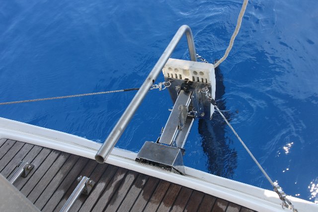
Not a very clear image , but the rudder test was done on the leg between the islands of El Hierro ( most south west canary island) and La Palma last summer. 2000 meters deep I took no chances of something breaking off and attached a safety line to the davits above . The sails were in and the engine speed was 5kts , the main rudder was in brake mode an neutral position , the E-rudder performed flawlessly and made 360 turns without hesitation .
www.23hq.com/sailbleu/photo/63231413/original
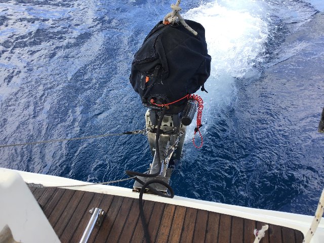
The E-propulsion test was done on the island La Gomera ( Canary islands). Safety line obligatory , and you will notice there was quite some cavitation going on due to the outboard not going deep enough . A formality as I have 3 height positions on the outboard mount , here the middle was used , obviously the lower level is required . The throttle was halfway and check the next photo for the speed result .
www.23hq.com/sailbleu/photo/63231714/original
Sailing from the quay to the anchorage in the bay on the west side of La Gomera , I made 2,6 kts , half throttle , and outboard not properly immersed , not bad for a 6 HP 4stroke outboard pushing an 8 ton boat don't you agree .
www.23hq.com/sailbleu/photo/63231959/original
This is where it all started , I call this the adapter plate ( right) and the back plate ( left) . The adapter plate will remain visible at all time , this will permanently stay on the transom and the required back plat will offer some strength as the transom fiberglass is fairly thin . I remember a youtube presentation of boaters that had to construct an E-rudder ( for real) as their main rudder was gone . Several times the captain had to re-fix , re-screw the supports of the E-rudder on the transom as the screws were pulled out by the forces on that E-rudder that in fact was a cupboard door. The back part of the boat is not very thick glassed so I figured some distribution of the forces was necessary .
www.23hq.com/sailbleu/photo/63232269/original
I welded some nuts on the back of the back plate to tighten the adapter plate . Then our puppet show started . Getting that back plate to inside of the post rudder area is/was a challenge .Bear in mind it had to be sicaflexed to prevent water ingress , so doing this correct was essential not to get the quadrant and surrounding area all covered with that nasty stuff . Like a puppeteer the admiral had to lower the back plate by the two top ropes into an inaccessible space and at the same time I pulled the two ropes on the middle holes to the inside of the transom so I could get the adapter plate screwed to it .
ww.23hq.com/sailbleu/photo/63232556/original
Mark the holes
www.23hq.com/sailbleu/photo/63232579/original
Holes drilled , ropes in and pushing them in further so the fishing could start .
www.23hq.com/sailbleu/photo/63232671/original
It's a bite
www.23hq.com/sailbleu/photo/63232717/original
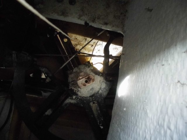
To give an idea of that maze inside . Obviously the back plate was too big to pass the hole for the main rudder stock , it had to sicaflexed , tight up and hanging without making a mess. Then lowered up to point where it touched the bottom and then I had to pulled it towards the inside of the transom . So a delicate synchronization job. Once I got one blot in we were home free .
www.23hq.com/sailbleu/photo/63232891/original
That wont go anywhere .
www.23hq.com/sailbleu/photo/63232911/original
This is option number 3 , see above on list of multiple purpose . I'll call it the dinghy step made of SS 316L sheet so it can stay on without oxidizing , the rest is made out of SS 304 that - as you know - stains after awhile .
The admiral always had some difficulties getting in or out the dinghy to and from the swim platform , this little SS accessory makes life easy for her . The arrows show where in a later stage I glued some anti slip patches on . Works great and the wife is happy , and when the wife is happy .....
www.23hq.com/sailbleu/photo/63233033/original
This photo tells the story .
www.23hq.com/sailbleu/photo/63233069/original
Rewind ( end of previous year) , back home I improvised a setup to copy the transom's angle so both the step and the outboard mount adapter are leveled . Also and very important the height to the water surface from the adapter plate Not being on the boat when I started the project I had to rely on the measurements given ( emailed ) to me by some friendly board members with a similar boat as we have . Thank you again Erkan , Alex and Chuck . The given numbers were correct , very helpful and allowed me to finish the project.
www.23hq.com/sailbleu/photo/63233392/original
As mentioned , knowing the exact angle of the transom with regards to the water surface ( the sea) was extremely important so both adapter and dinghy step are perfectly leveled .
I made a carton template , tried it on the wooden setup and then took it apart as a model for the SS sheet .
www.23hq.com/sailbleu/photo/63233628/original
Crucial angle !
www.23hq.com/sailbleu/photo/63233656/originalNice puzzle
www.23hq.com/sailbleu/photo/63233674/original
The outboard-mount-adapter gradually getting together, the four pieces of threaded rod you see are actually short bolts welded to the in side of the adapter, each side of the adapter has a set of 4 . They're there to hold the slats in place. These slats slide in the adapter plate holders like a cupboard drawer .
www.23hq.com/sailbleu/photo/63233924/original
www.23hq.com/sailbleu/photo/63233956/original
www.23hq.com/sailbleu/photo/63233984/original
I forgot to mention that on this side of the adapter , the visible side , I welded nuts on the inside to screw on the base of the engine mount itself .
www.23hq.com/sailbleu/photo/63234033/original
It falls in place , note the red arrow , this an on welded stop to prevent the adapter ( and dinghy step) to drop to the rub rail where it could cause damage after awhile .
www.23hq.com/sailbleu/photo/63234147/original
Time for the E-rudder itself, where to start ? A piece of marine plywood and a rudder stock , or is it a rudder trunk , not sure ?
www.23hq.com/sailbleu/photo/63234198/original
Some research have led me to believe this shape is the most efficient shape for a rudder. Other research pointed out that the surface of an E-rudder should be 2/3 of that of the main rudder. I can now say to disagree with the surface theory. After my tests I find 50% of the main rudder is more than enough to get the boat steered . My luck is that I can raise the E-rudder so less surface is exposed to the water pressure . I'm convinced the first (highest) position on the mount is adequate to keep the boat's manual heading .
www.23hq.com/sailbleu/photo/63237187/original
No harm no foul . If it doesn't help it doesn't harm . What I trying to say it that some fiber glassing can only add to the strength of the rudder .
www.23hq.com/sailbleu/photo/63235627/original
One side done , flip side to go .
www.23hq.com/sailbleu/photo/63235652/original
Time to address the stock and bearing . I've cut some segments out to fit over the E-rudder and drilled four holes .
www.23hq.com/sailbleu/photo/63235714/original
www.23hq.com/sailbleu/photo/63235754/original
Once the fiberglass had cured I gave the rudder four coats of black dyed epoxy resin , seal it .
www.23hq.com/sailbleu/photo/63235806/original
How to fix the rudder to the mount ? The smaller plate with the 3 holes on the right hand side of the picture will be bolted to the mount. Seen next pics.
www.23hq.com/sailbleu/photo/63235858/original
www.23hq.com/sailbleu/photo/63235901/original
Try getting a hole this size without a proper sized drill or plasma cutter , cutting and grinding is an alternative.
www.23hq.com/sailbleu/photo/63235958/original
The lock pin allows the stock to come apart from the rudder , easy for storage.
www.23hq.com/sailbleu/photo/63236041/original
Important photo , the stock guide bearing is there for some additional support and to keep everything together . Unfortunately, the test showed this support was not up to the task . Therefor I had to reconfigure this bearing .
Btw the nut above is for the suspension between stock and outside top of the E-rudder. See photo down
www.23hq.com/sailbleu/photo/63236177/original
Only this feeble black nut preventing the complete rudder to swing from left to right , that didn't work .
www.23hq.com/sailbleu/photo/63236222/original
I took the bearing off and welded it on an SS plate the shape of the mount . I yet have to drill the correct holes when we get back to the boat in May as most of the parts remained on board.
www.23hq.com/sailbleu/photo/63236287/original
To illustrate how the outboard mount ( with E-rudder ) is held in position . Cross SS wires with tensioners stop any movement .
www.23hq.com/sailbleu/photo/63236381/original
I managed to attach the wires on eye bolts on the davits base plates .
www.23hq.com/sailbleu/photo/63236418/original
A view on the E-rudder stock >> and E-rudder itself
www.23hq.com/sailbleu/photo/63236473/original
www.23hq.com/sailbleu/photo/63236503/original
www.23hq.com/sailbleu/photo/63236527/original
Hope you enjoy this contribution
Kind regards


