

The nautical multitool
Feb 27, 2010 8:38:24 GMT
Post by sailbleu on Feb 27, 2010 8:38:24 GMT
Because I had to replace the cutless bearing , and also some other adjustments on the prop-shaft , I tought of making a tool that would simplify and combine all of these worlds.
So the multitool-idea popped up.
Allow me show it to you.
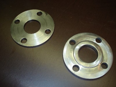
We take an ss flange and cut in 2 so we get 2 thinner flanges.
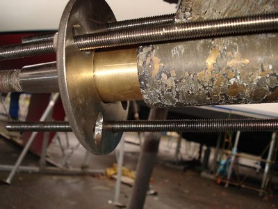
On those flanges a spacer is welded so the inner diameter becomes smaller to the desired size.
On the back of one flange , lets call it flange 1 , a ring is welded to reduce the diameter so the other parts (next pic) will fitt in.
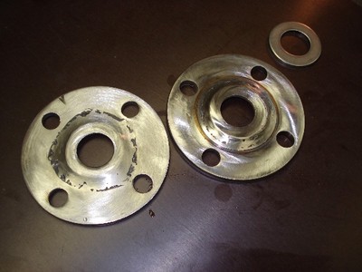
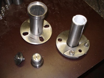
This is the part (half of it anyway) that will push out the cutless bearing.
The complete set .
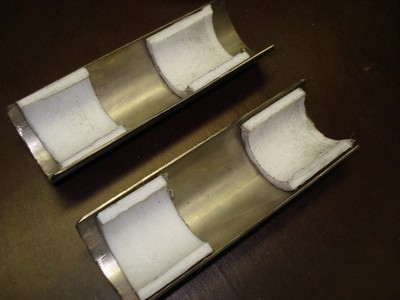
Inside both parts spacers are glued so the exact innner diameter is 30 mm , being the thickness of the propellershaft. All will become clear later on.
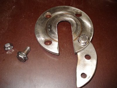
A segment is cut from flange 1 so it fits over the shaft.

Also a bridge is made to close the gap.
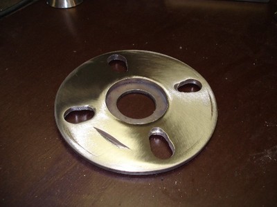
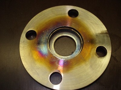
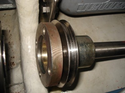
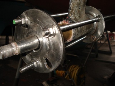
This is the second flange , lets call it flange 2 . as you can see the holes are made bigger towards the inside of the flange. Has to do with a different size of flange on the transmission.Again , it will become clear later on.
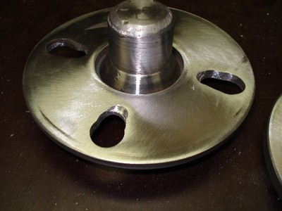
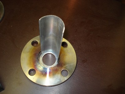
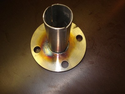
A nipple is made to fit flange 2 .
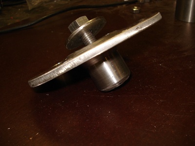
This is how the nipple is attached to the flange.
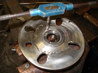
In that same flange a hole is drilled and thread is cut so another part can be fixed onto that flange.
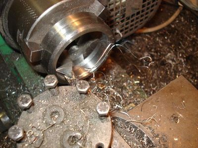
It involved some serious work in order to produce that other part.
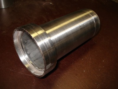
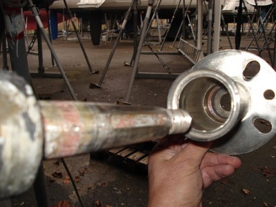
This is it. A pipe that can hold the cutless bearing and the open end is big enough to be put over the strut.
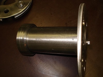
This pipe can be fixed on to flange 2 as you can see.
Ok, here's a picture of the complete multitool , thread rods not included.
Lets use it now. The comming pics will show the application of all those separate parts.
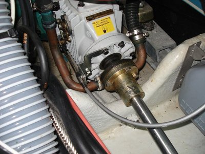
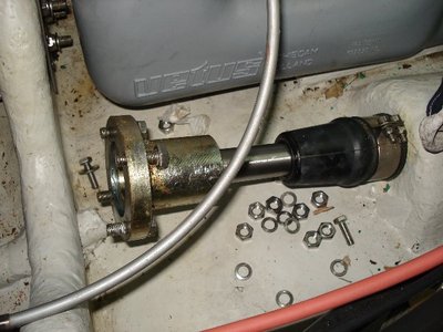
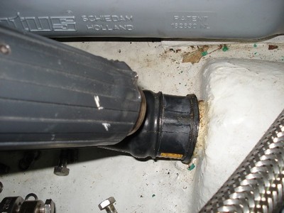
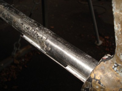
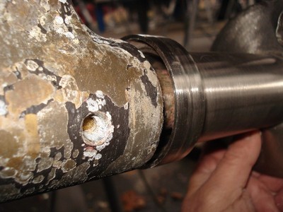
Familiar view for many of us right ? The transmission , flange and propellorshaft.
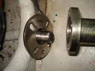
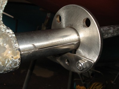
Flange disconnected.
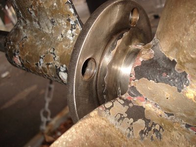
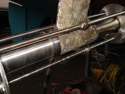
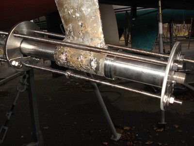
Flange 2 with nipple part is positioned , but not before the nut – fixing the flange to the shaft - is removed.
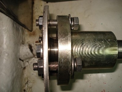
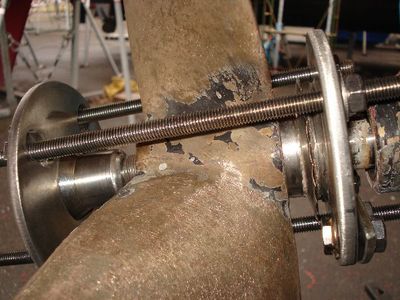
Bolts are screwed in.
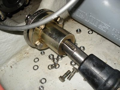
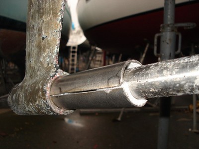
The bolts are tightened and the nipple has pushed the shaft out of the flange.
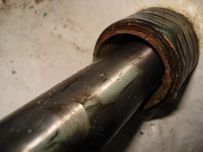
And because the ‘ line ‘ is open we might aswell replace the volvo gland. First heating it up and then gently removing it.
Job done.
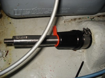
New gland is put in , using the protective orange plastic component so the inside of the gland is not damaged while sliding it over the shaft. The orange doda will remain in place untill all labour is done.
Not forget to grease the inside of the gland.
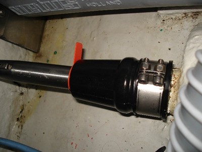
Different angle.
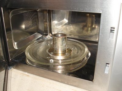
Now the transmission flange is being heated up in the oven so its really thight on the shaft.
But before putting on the flange , I needed to slide over the handmade pulley which will be used to drive my propeller shaft generator. (That will be my next contribution)
Next appication of the multitool.
Removing the propeller.
The rope-cutter is released , and slided towards the propeller, creating enough space to put in flange 1.
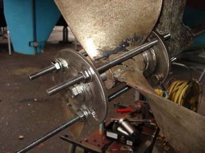
Flange 2 with nipple also in position.Thread rods holding everything together.
It’s nut-turning-time.
Ok; next application.
Pushing out the cutless bearing.
Remember the shaft-shells ? One half is put on the shaft.
Second half is in place.
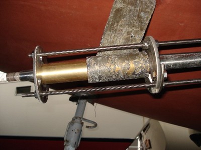
Gently slide the set into the strut.
Flange 1 over the shaft and bridge is closed.
At the end of the shaft the cutless bearing–holder is slided over the shaft.
Ready to go.
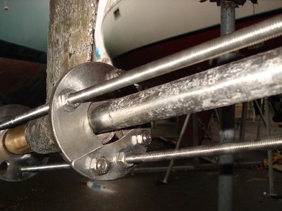
Again , thread rods in place.
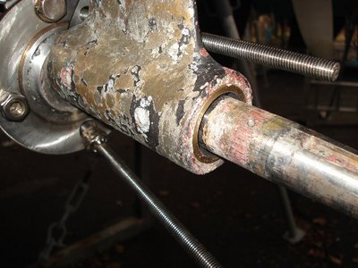
Turn the nuts and push the cutless bearing out of the strut into the holder.
Now the new bearing is ready to go in.
Different angle.
Another angle.
And once again screwing the nuts and pusshing in the cutless bearing.
Mission accomplished.
And last but not least, fixing the cutless bearing with the screws on the side of the strut.
No need for pictures i presume.
So , I hope this sort of guide can help other sailers as far as doing some maintenance with the proper tool(s) concerns
So the multitool-idea popped up.
Allow me show it to you.
We take an ss flange and cut in 2 so we get 2 thinner flanges.
On those flanges a spacer is welded so the inner diameter becomes smaller to the desired size.
On the back of one flange , lets call it flange 1 , a ring is welded to reduce the diameter so the other parts (next pic) will fitt in.
This is the part (half of it anyway) that will push out the cutless bearing.
The complete set .
Inside both parts spacers are glued so the exact innner diameter is 30 mm , being the thickness of the propellershaft. All will become clear later on.
A segment is cut from flange 1 so it fits over the shaft.
Also a bridge is made to close the gap.
This is the second flange , lets call it flange 2 . as you can see the holes are made bigger towards the inside of the flange. Has to do with a different size of flange on the transmission.Again , it will become clear later on.
A nipple is made to fit flange 2 .
This is how the nipple is attached to the flange.
In that same flange a hole is drilled and thread is cut so another part can be fixed onto that flange.
It involved some serious work in order to produce that other part.
This is it. A pipe that can hold the cutless bearing and the open end is big enough to be put over the strut.
This pipe can be fixed on to flange 2 as you can see.
Ok, here's a picture of the complete multitool , thread rods not included.
Lets use it now. The comming pics will show the application of all those separate parts.
Familiar view for many of us right ? The transmission , flange and propellorshaft.
Flange disconnected.
Flange 2 with nipple part is positioned , but not before the nut – fixing the flange to the shaft - is removed.
Bolts are screwed in.
The bolts are tightened and the nipple has pushed the shaft out of the flange.
And because the ‘ line ‘ is open we might aswell replace the volvo gland. First heating it up and then gently removing it.
Job done.
New gland is put in , using the protective orange plastic component so the inside of the gland is not damaged while sliding it over the shaft. The orange doda will remain in place untill all labour is done.
Not forget to grease the inside of the gland.
Different angle.
Now the transmission flange is being heated up in the oven so its really thight on the shaft.
But before putting on the flange , I needed to slide over the handmade pulley which will be used to drive my propeller shaft generator. (That will be my next contribution)
Next appication of the multitool.
Removing the propeller.
The rope-cutter is released , and slided towards the propeller, creating enough space to put in flange 1.
Flange 2 with nipple also in position.Thread rods holding everything together.
It’s nut-turning-time.
Ok; next application.
Pushing out the cutless bearing.
Remember the shaft-shells ? One half is put on the shaft.
Second half is in place.
Gently slide the set into the strut.
Flange 1 over the shaft and bridge is closed.
At the end of the shaft the cutless bearing–holder is slided over the shaft.
Ready to go.
Again , thread rods in place.
Turn the nuts and push the cutless bearing out of the strut into the holder.
Now the new bearing is ready to go in.
Different angle.
Another angle.
And once again screwing the nuts and pusshing in the cutless bearing.
Mission accomplished.
And last but not least, fixing the cutless bearing with the screws on the side of the strut.
No need for pictures i presume.
So , I hope this sort of guide can help other sailers as far as doing some maintenance with the proper tool(s) concerns


